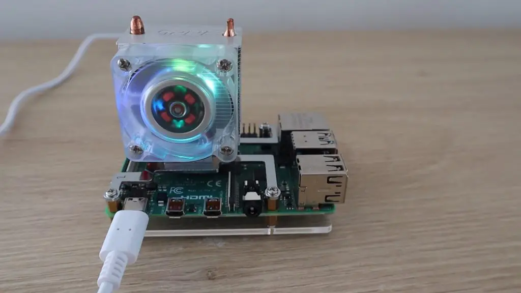
A couple of weeks ago I built a single water cooled Raspberry Pi 4 just to see how well it would work. This was obviously crazy overkill for a single Raspberry Pi, but it isn’t actually why I bought the water cooling kit. I bought it along with 7 other Raspberry Pi 4Bs so that I could try building my own water cooled Raspberry Pi 4 Cluster.
Here’s my video of the build, read on for the write-up:
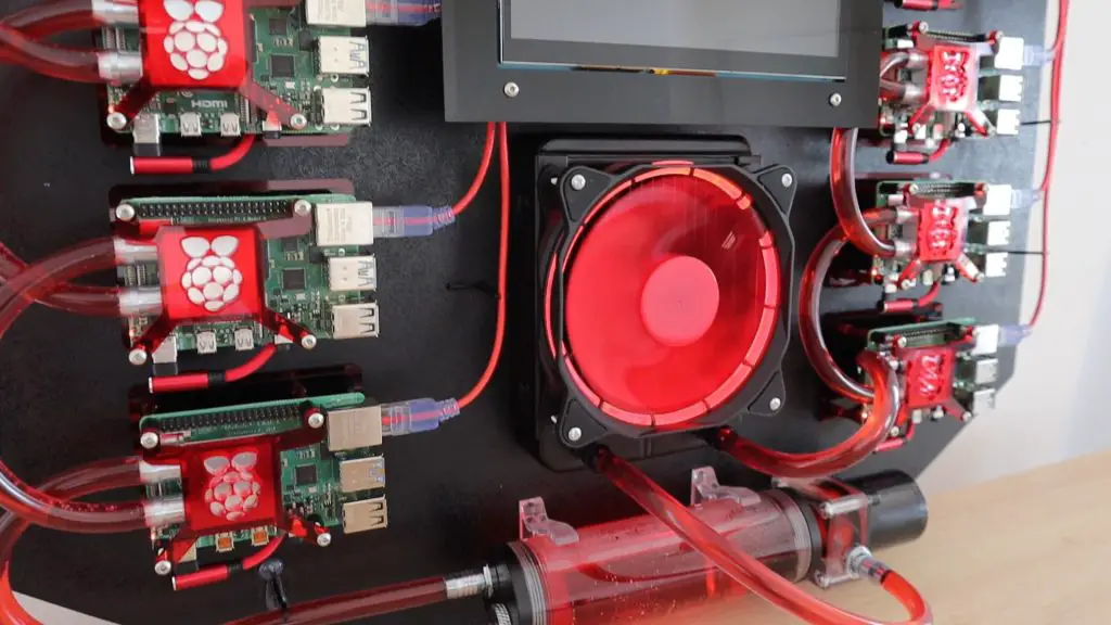
While water cooling a single Raspberry Pi doesn’t make too much sense, water cooling a whole cluster is a bit more practical. The whole system is cooled by a 120mm fan, which is significantly quieter than even a single small 40mm fan. The water cooling system, while expensive by itself, actually costs a bit less than some other cooling solutions, given that I’d have to buy 8 of them.
An Ice Tower is an effective cooling solution for an individual Pi, but they’re quite noisy, and at around $20 each, you’re looking at $160 just for cooling the cluster. The water cooling system was only around $85 for the whole kit, blocks, and additional tubing.
For those of you who don’t know what a Pi Cluster is, it’s essentially a set of two or more Raspberry Pi’s which are connected together on a local network and work together to perform computing tasks, by sharing the load.
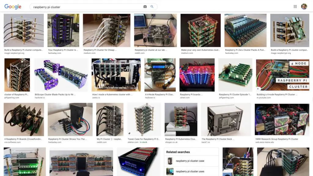
There is usually one Pi which is designated as the host or master node and it is in charge of breaking up the task into smaller tasks and sending these out to all of the nodes to work on. The master node then compiles all of the completed tasks back into a final result.
The Parts I Used To Build My Cluster
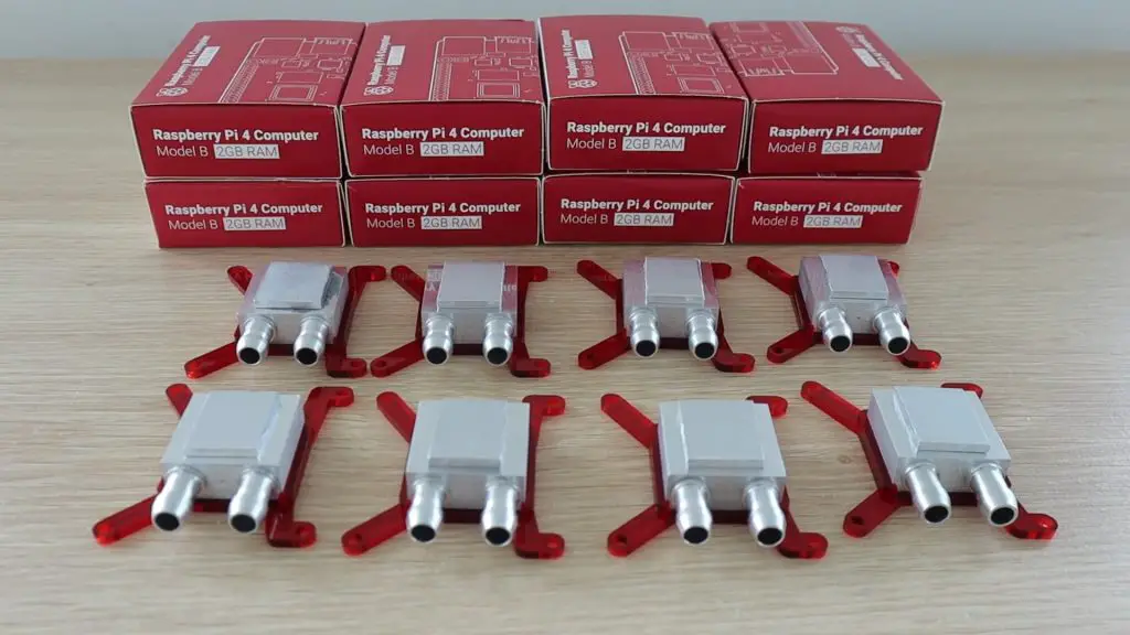
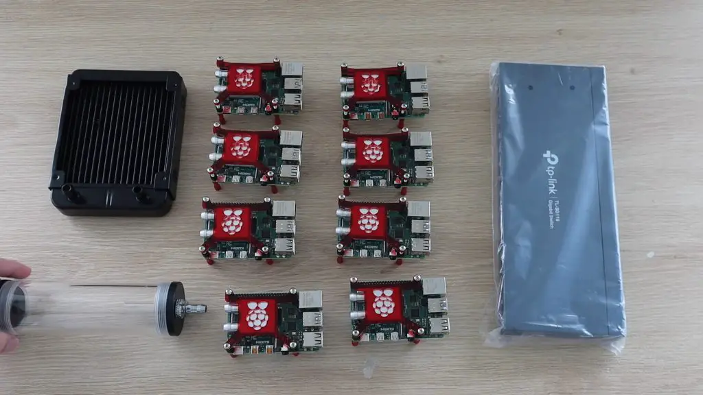
To build my cluster, I got together 8 Raspberry Pis, a network switch, a USB power supply, and then the water cooling kit, cooling blocks and a bunch of network cables, USB C cables, standoffs, and screws to put it all together.
I also used a 3mm MDF board and some wood sections I had lying around to make up the mounting board and frame.
- 8 x Raspberry Pi 4B (2GB Model Used) – Buy Here
- TP-Link 16 Port Ethernet Switch – Buy Here
- Rav Power USB Charging Hub – Buy Here
- HD Touchscreen Monitor – Buy Here
- Water Cooling Kit – Buy Here
- 8 x 30mm Cooling Blocks – Buy Here
- 8 x Ethernet Patch Leads – Buy Here
- 8 x USB C Cables – Buy Here
- 3m RGB LED Strip – Buy Here
- M3 Standoff Mount Kit – Buy Here
- M3 Screw Kit – Buy Here
- 3mm MDF Board Approx. 600 x 600mm
Building The Raspberry Pi 4 Cluster
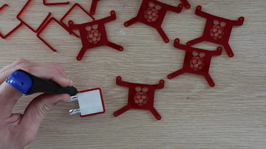
Making & Assembling the Cooling Block Brackets
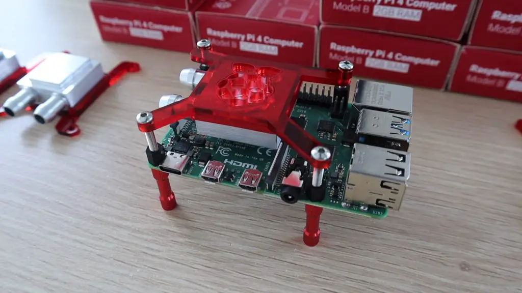
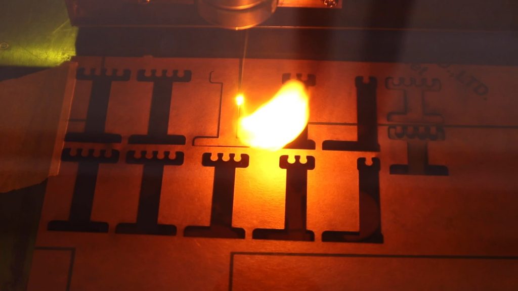
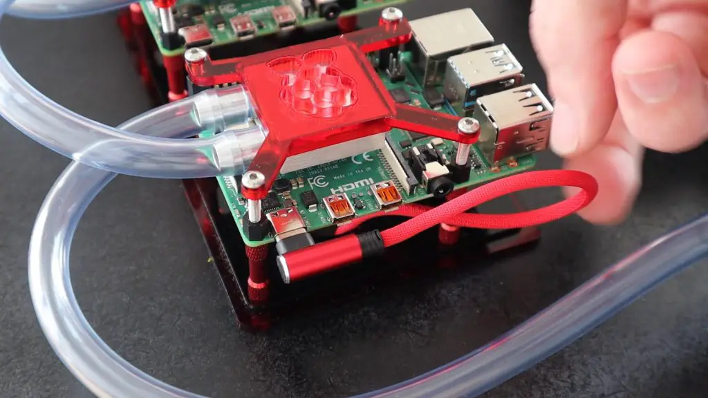
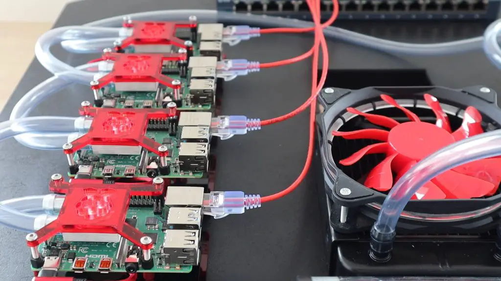
I started off by making up the 8 acrylic brackets to hold the cooling blocks in position over each Pi’s CPU.
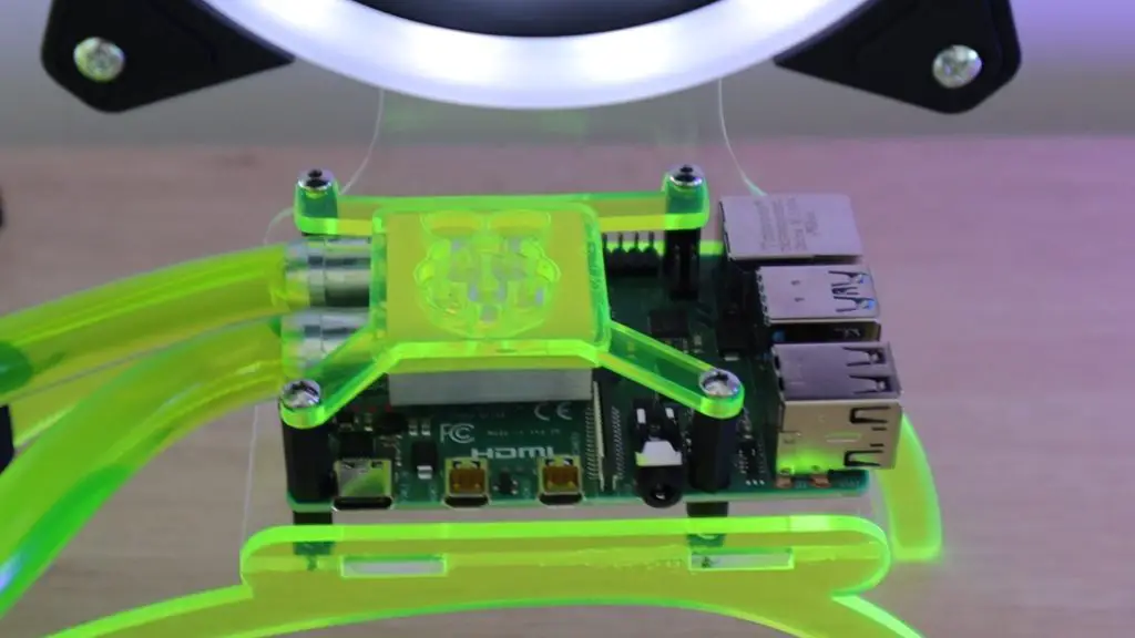
These are the same design as the one used previously for my single Raspberry Pi, but are now red to suit the cables and fan.

Each bracket consists of two parts which are glued together to hold the cooling block in place.
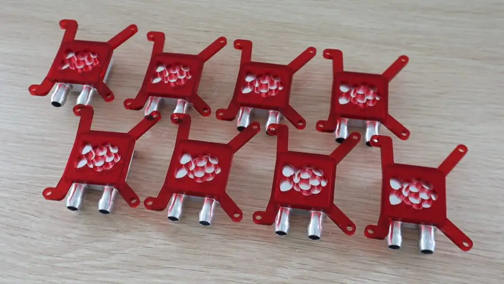
I also had to include a spacer to lift the cooling block a bit higher off the CPU so that it clears the surrounding components, otherwise, I’d have to remove the display connector from all 8 Raspberry Pis. I used a bit of thermal paste between the blocks and the spacers.
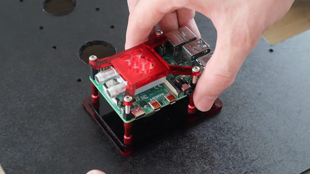
The cooling blocks were then mounted onto the Raspberry Pis. I started by securing the Pi between some red aluminium standoffs, which would be used to mount the Pi onto the base, and some nylon standoffs for the cooling block to screw into.
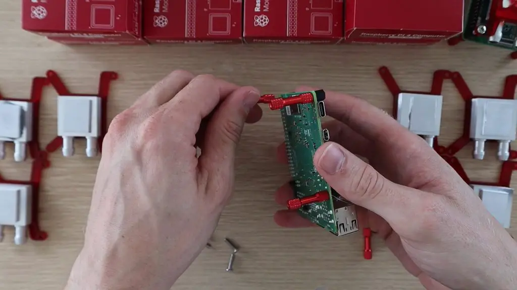
The bracket picks up on the hole on the standoffs and clamps the cooling block down onto the Pi’s CPU.
I then repeated this 7 more times for the other Pis needed to build the 8 node Raspberry Pi 4 Cluster.
Deciding on the Cluster Layout
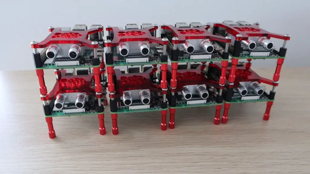
The traditional way to build a cluster is to place standoffs onto each Pi and then mount them on top of each other to form a stack. This is the easiest and most compact way to assemble them, but doesn’t really work that well with my cooling block bracket and isn’t all that eye-catching.
This got me thinking of a way to better layout the Raspberry Pi 4 Cluster so that the cooling water circuit was clearly visible and the cluster was both functional and eye-catching. It would be even better if it could be mounted onto a wall to form a hang-up feature.
I played around with a couple of layout options, considering the placement of the components to minimise cable and tube lengths and trying to maintain some symmetry to keep it looking neat.
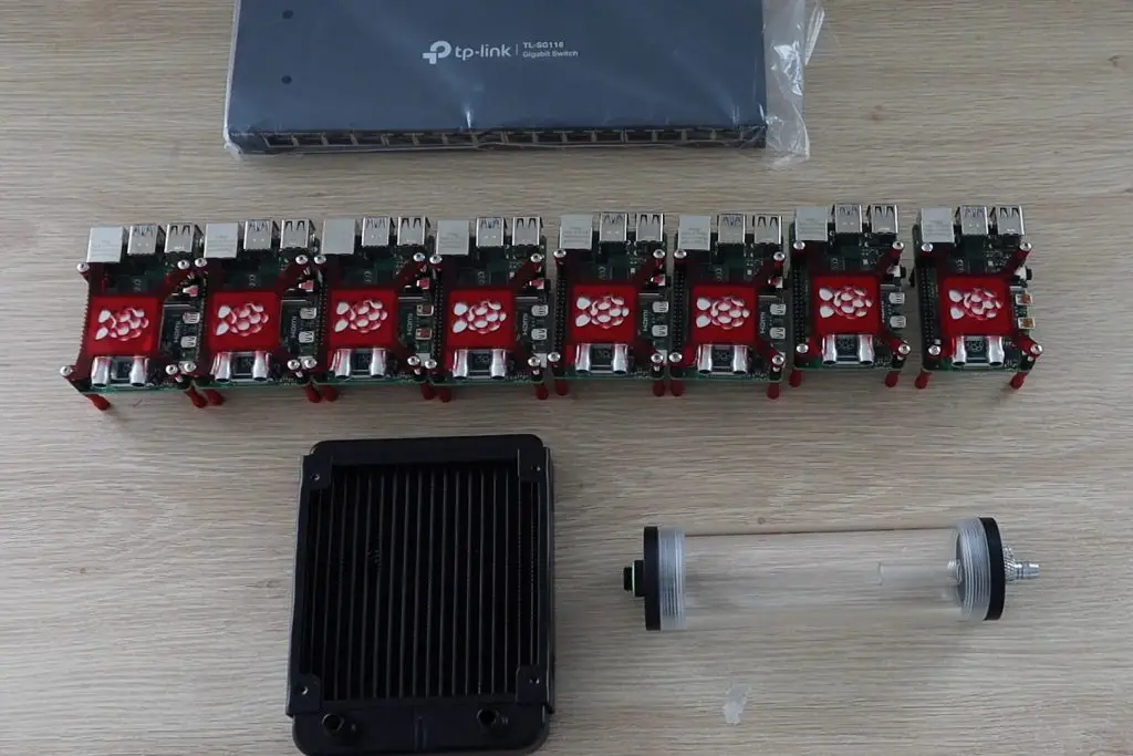
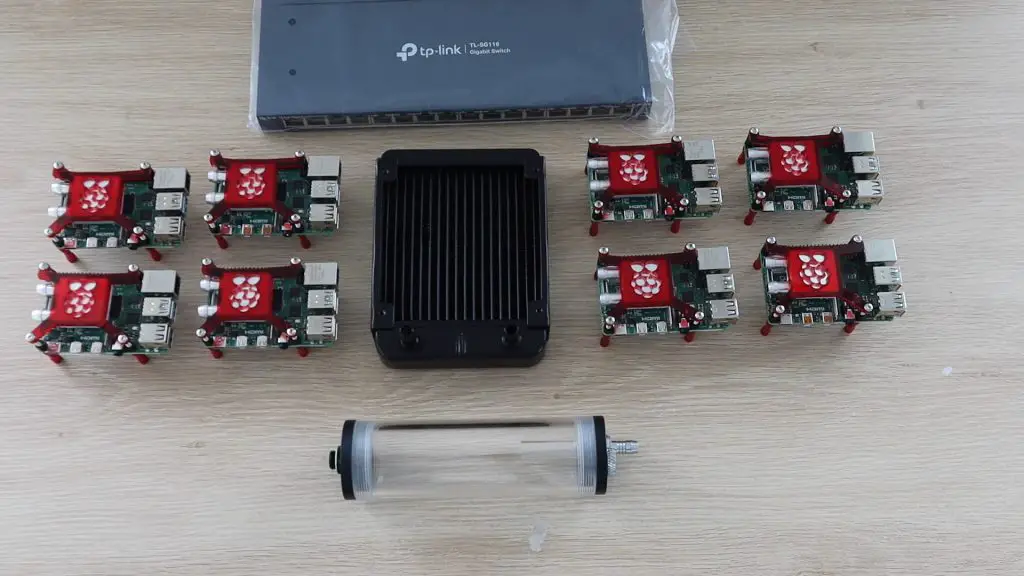
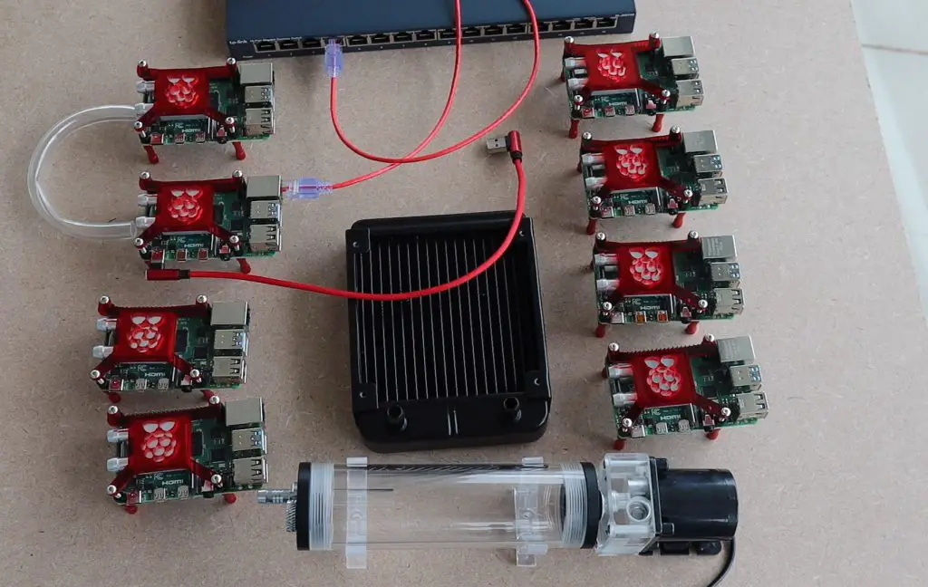
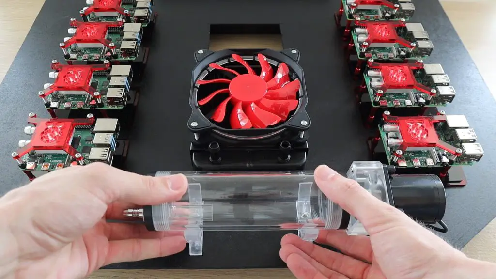
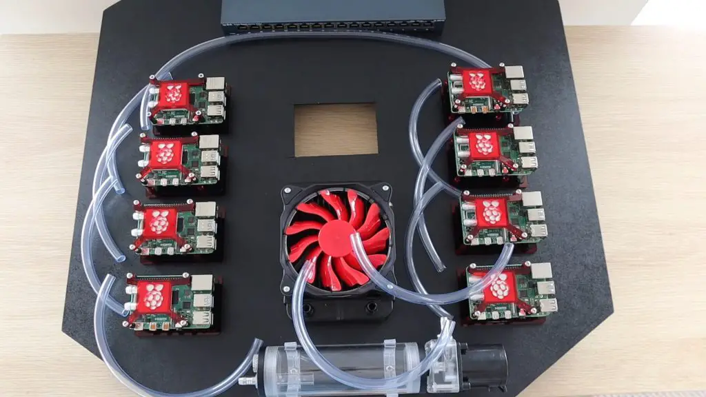
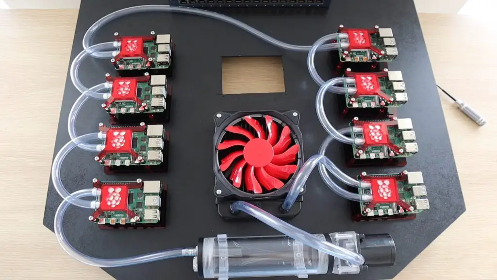
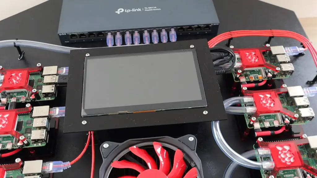
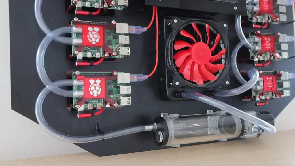
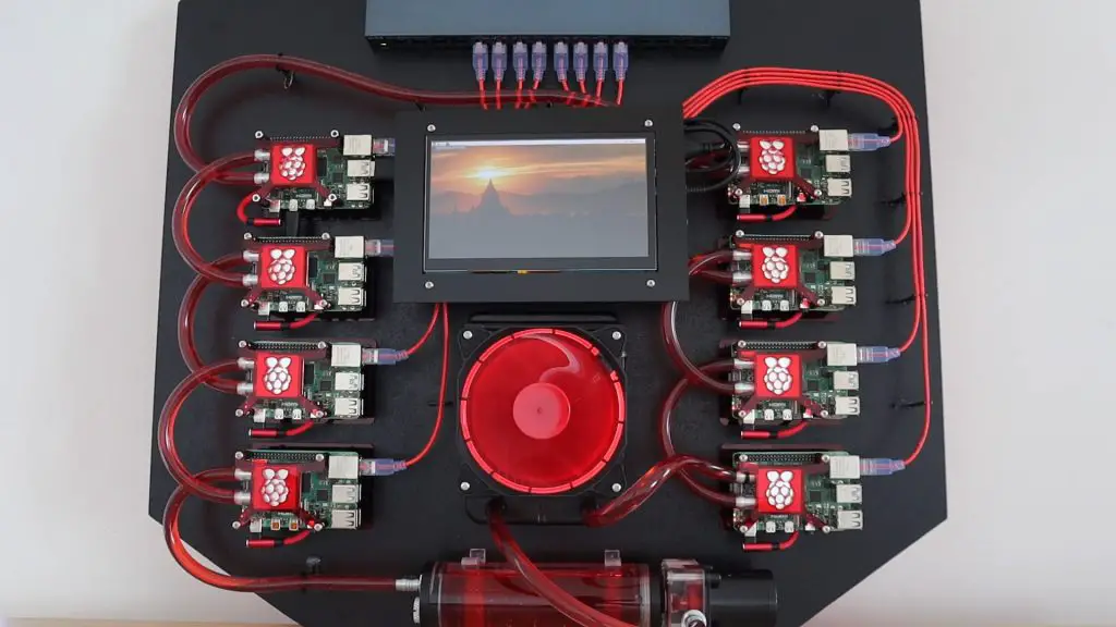
I settled for having four Pi’s on each side of the radiators, keeping the large fan as the focal point in the design. I’d then put the reservoir and pump underneath the radiator to circulate the water through the loop. The Ethernet switch would be positioned at the top of the cluster to feed the network cables down to each node.
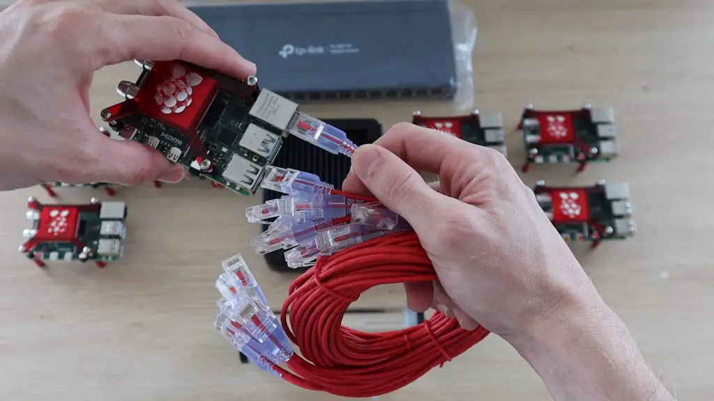
I’d be connecting the Pi’s to the switch using some red patch leads. I found some red 50cm low-profile leads which looked like they would work well for this application. The thinner leads meant that that excess cable could be coiled up a bit easier and the runs were really short, so conductivity wasn’t a big issue.
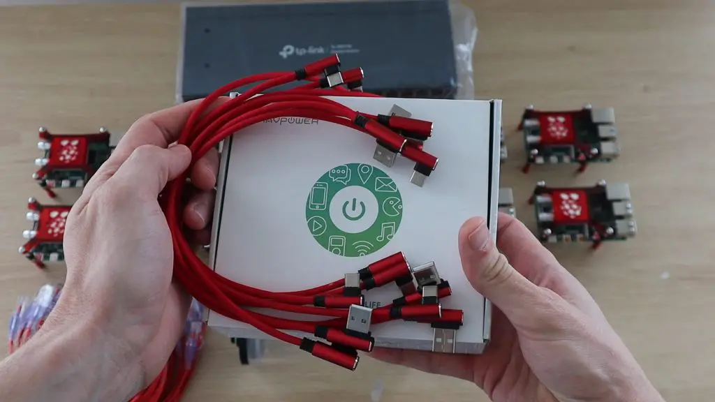
To power the Raspberry Pis, I bought a high power USB charging hub and some short USB C cables. The hub provides up to 60W, distributed over 6 ports. I couldn’t find a suitable 8 port one, so settled on splitting two of the ports into two.
I’d also have to keep an eye on the power consumption as the official power supply for the Pi 4B is a 3 amp, so a bit more than this hub could supply to each. But, I have also never seen one of my Pis run over 1 amp in practice, even under load. If need be then I could buy a second power supply down the line.
Positioning the Pis on the Back Board
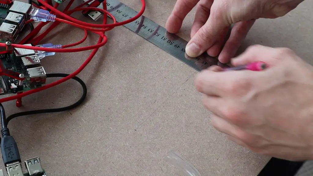
Once I had my layout in mind, I started making the backboard. I positioned all of the major components onto a piece of 3mm MDF and then marked out where they would be placed and the holes needed to mount them.
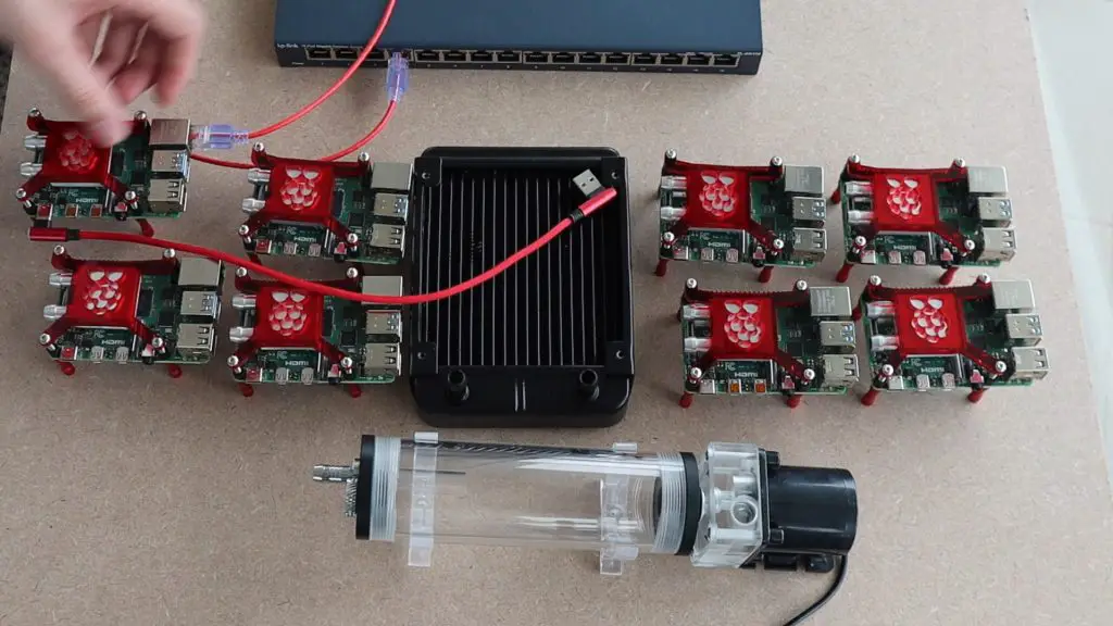
I checked the clearances required for the cables and then started planning the cooling water tube routing. It was at this point that I realised that having four Pi’s arranged in a square would result in an unnecessarily complex cooling water loop, and I switched to having the four Pi’s in a straight line on each side. With the four in a line, the tubing could just be looped from one to the next along each side.
I also had to make a decision on how best to run the cooling water loop. If I put each Pi in series then the first will be the coolest in the loop and each will get progressively warmer, with the last one running the warmest. If I put the Pi’s in parallel then they’ll all receive the same temperature water, but balancing the flow rates becomes a problem and it’s quite likely that one or two which are the furthest away would receive little to no flow through them. I decided that warm water was better than no water and I didn’t want to buy 8 valves to try and balance the flow rate between them, so I set out connecting them in series.
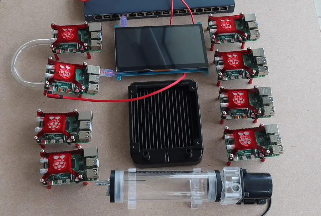
I also had a gap at the top where there was a lot of spare space, so I decided to pull out an old touch panel which I had used on a previous project. Having a display for the master node meant that I would have a way to monitor the system and even display stats, graphs or diagnostics directly on the cluster.
I then marked out the positions for each of the components on the back board and their mounting holes.
Making the Back Board
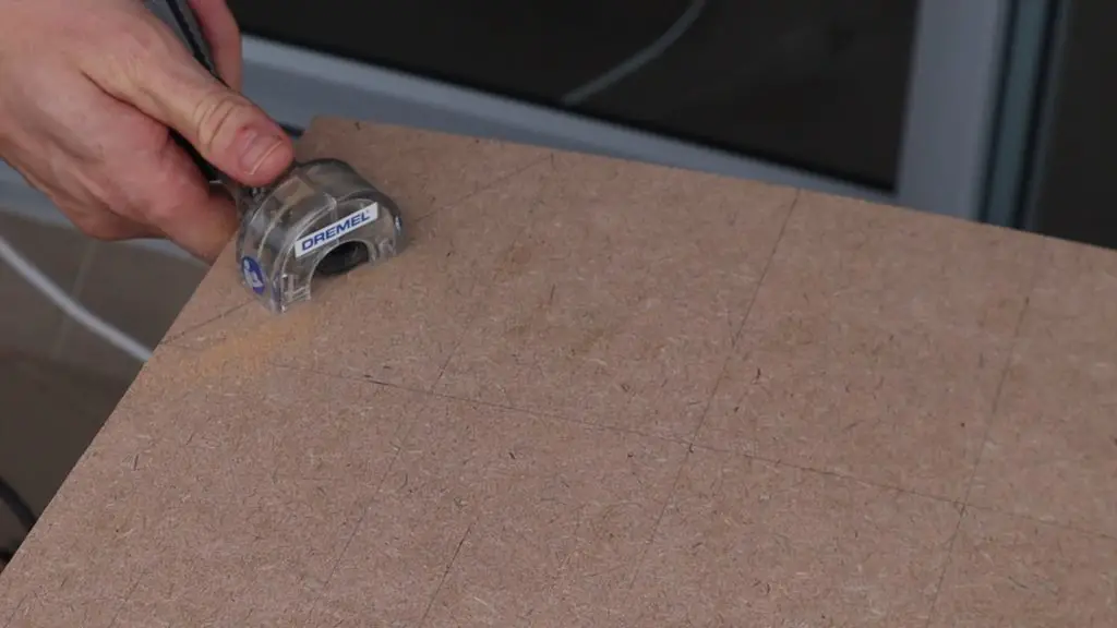
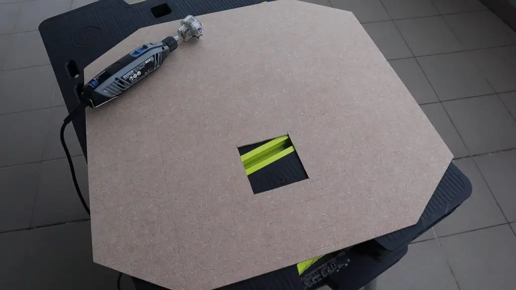
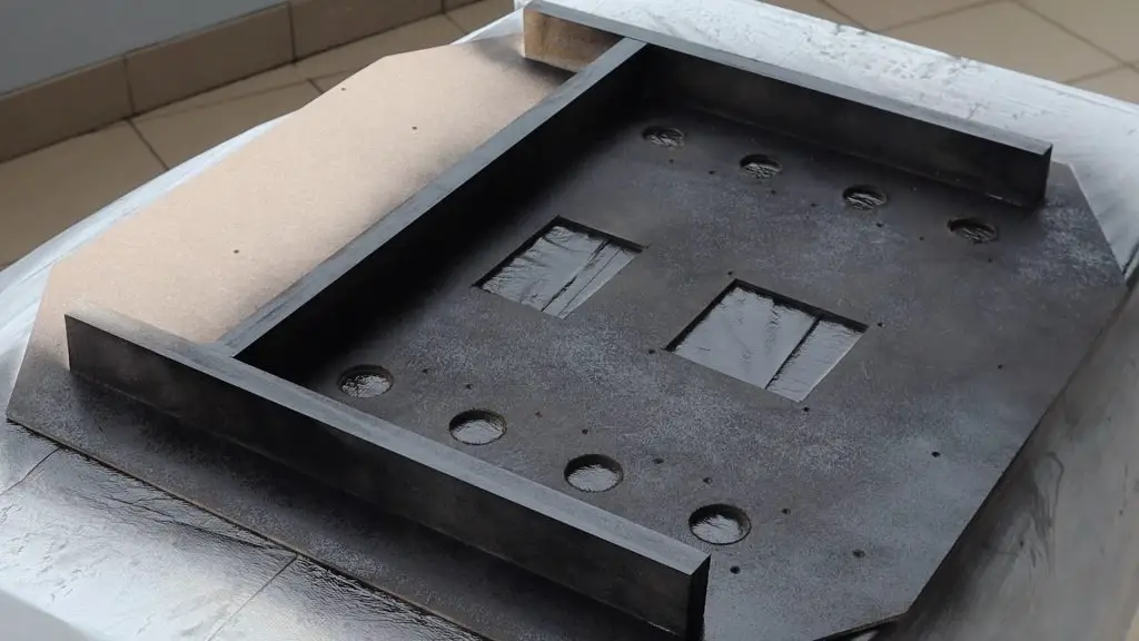
I decided to cut the corners off of the back board to give it a bit more of an interesting shape. I used a Dremel to cut the board to size, cut the corners off and cut a section out of the middle for the airflow through the radiator.
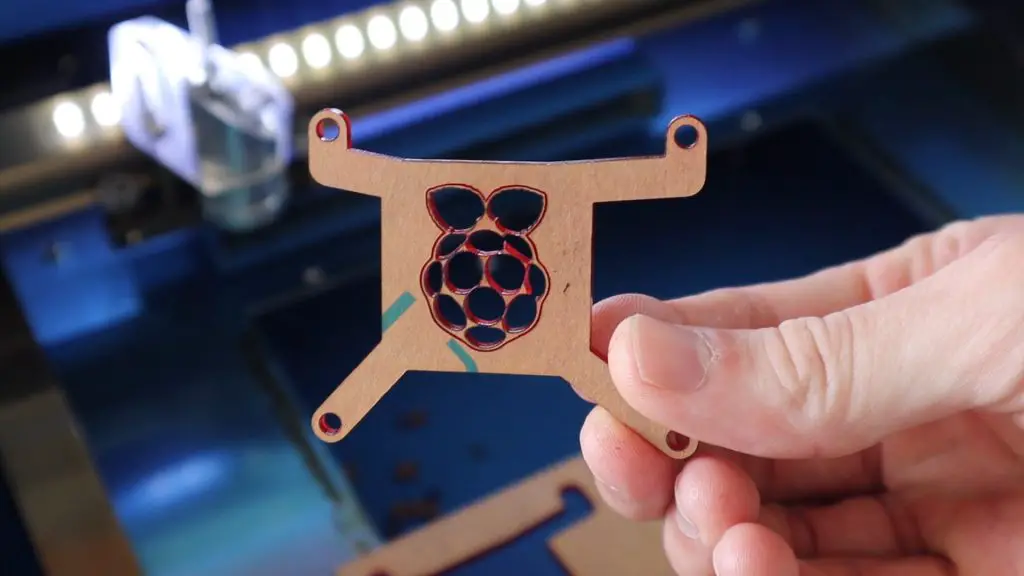
To mount the Raspberry Pi’s onto the board, I decided to design and laser cut a small acrylic base to add a red accent and guide the power cable through to the back.
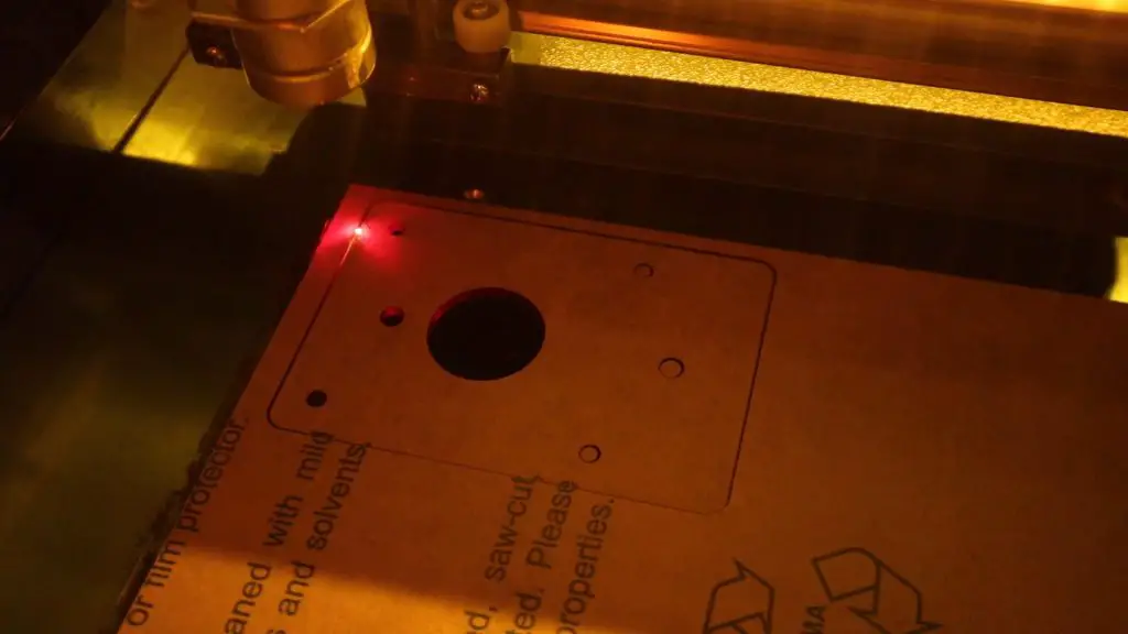
Each base consists of a red bottom layer and a black top layer, which were glued together with some acrylic cement.

I also designed a couple of cable and tube management stands to help with the routing of the cables and the tubes.
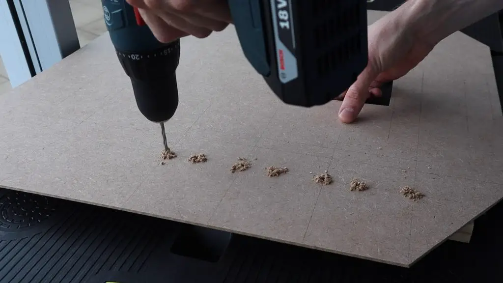
I then checked all of the positions of the mounting holes and drilled them out.
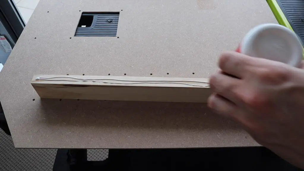
I decided to add some wooden sections to the back of the board to stiffen it and to create an area behind the board for cable management and the power supply. I used a spare section 0f 40mm x 20mm pine which I cut into three sections.
I made holes underneath the acrylic bases for the USB cables to run through. These aligned with the large hole in the acrylic bases.

To complete the back board, I sprayed the front and back of the board black.
Assembling the Raspberry Pi 4 Cluster Components onto the Back Board
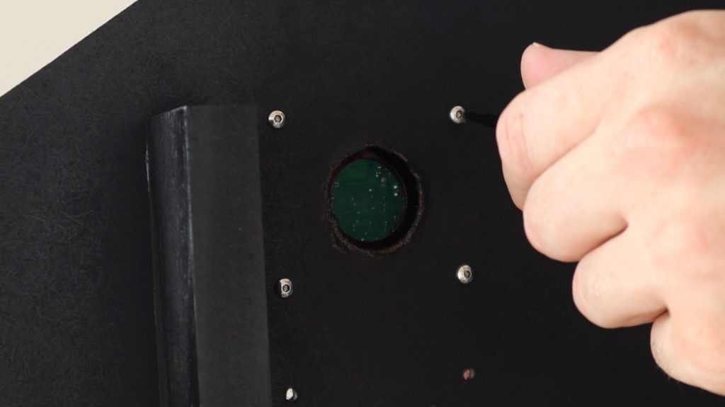
I then mounted the Pis, the network switch and cooling water components onto the back board.
Each Pi was secured using four M3 x 8mm button head screws, which screwed into the aluminium standoffs.
The cooling water components were mounted with the fasteners which came in the kit.
I then cut the cooling water tube to the correct lengths and pushed them onto the fittings.
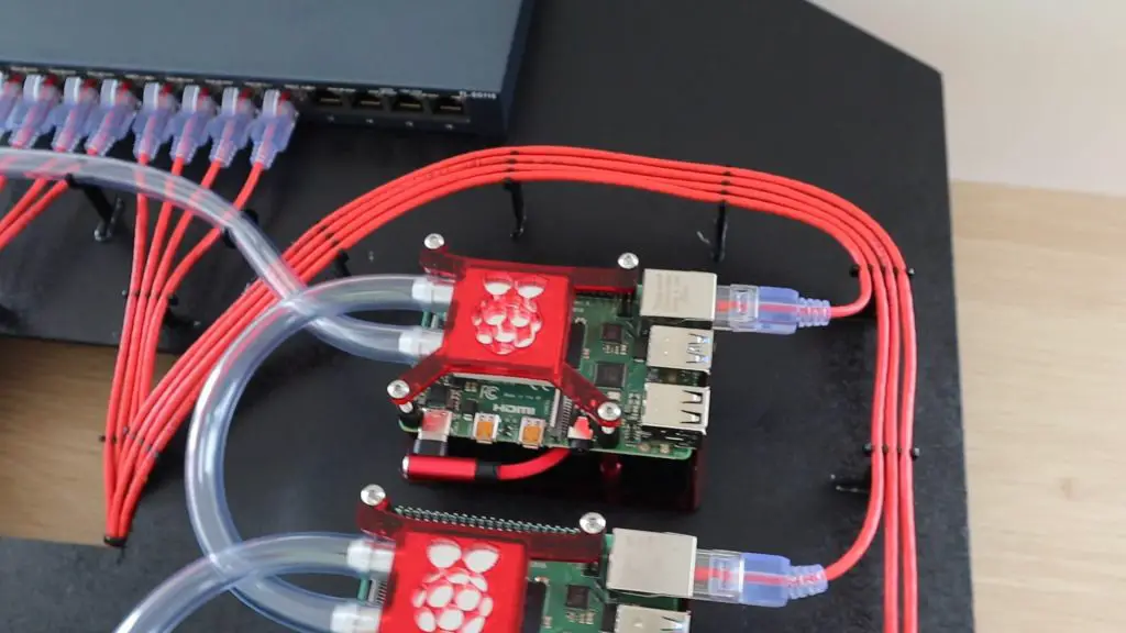
I could then start adding the Ethernet and power cables. I started by plugging a USB C cable into each Pi and routing these to the back of the board, where I mounted the USB hub.
I then added an Ethernet cable to each Pi, routing these up each side and into the cutout which would be behind the display, before bringing them back out to the front of the board and up to the switch. This meant that the excess cabling could be coiled up behind the board, out of ordinary sight.
I used the acrylic stand which I had cut out to hold and guide the Ethernet cables.
The last thing to add was the display, which I mounted on an acrylic face panel with some acrylic side supports to hold it in place.
You’ll notice that I had to mount the master node a bit lower than the others so that I could get the HDMI cable in without clashing with the Pi next to it.
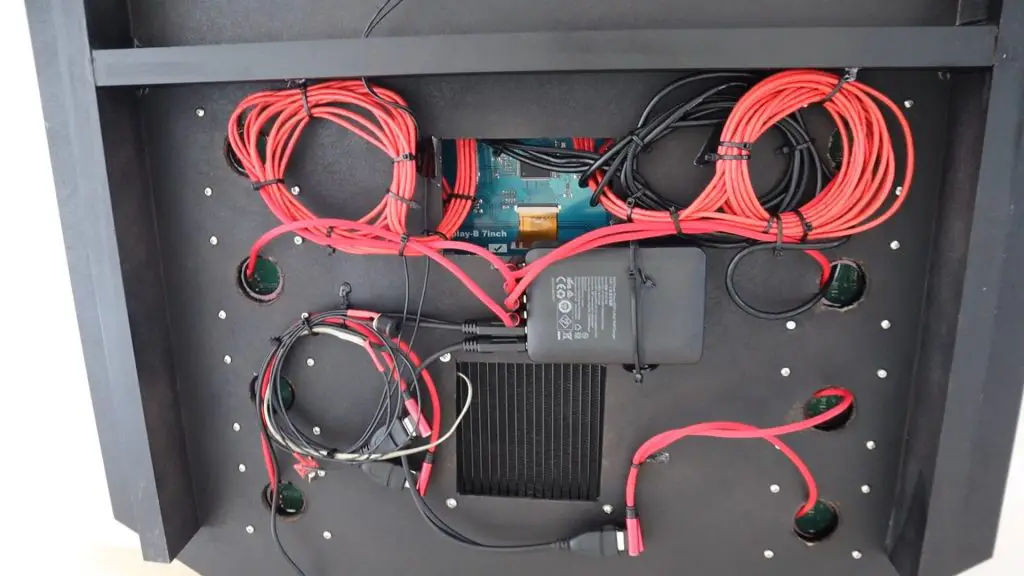
I tied up all of the cables at the back of the cluster using some cable ties and some cable holders which I cut from acrylic and glued into place. The cabling at the back isn’t particularly neat, but it would be out of sight in any case.
I also made up a connector to take the 12V supply from the switch and split it off to power the 120mm fan and cooling water pump. They only draw around 150mA together while running, so there was some extra capacity in the power supply.
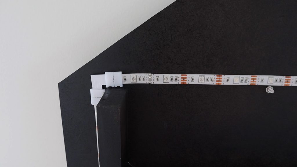
As a final touch, I added an RGB LED strip to the back to create some accent lighting on the wall behind it. The strip has an RGB remote control with a number of colours and features, but I was only going to be using the red LEDs.
Filling The Cooling Water Loop Up
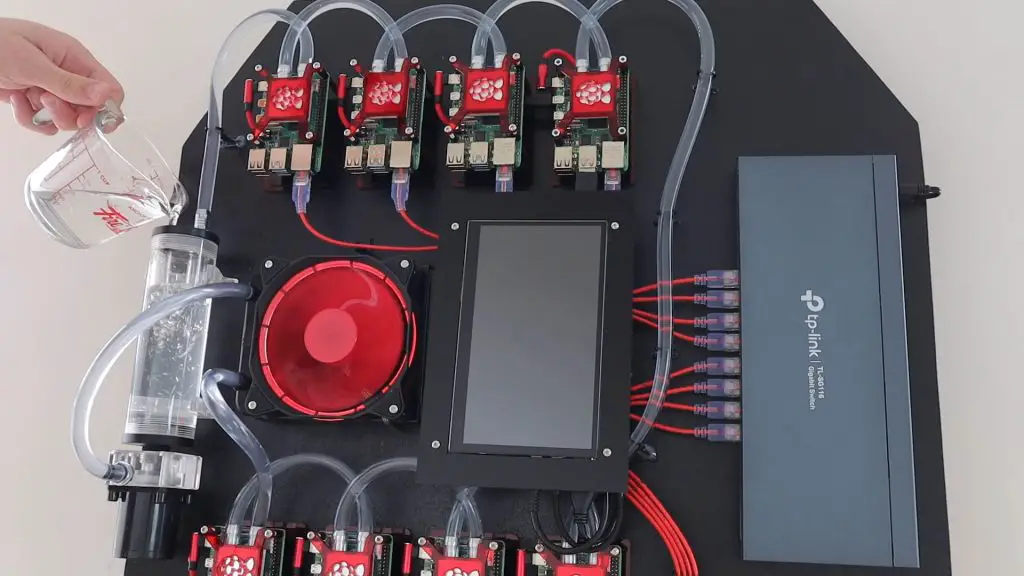
With all that done, I just need to fill the cooling water circuit and hope that I didn’t drown one of the Pis. I had visions of filling it up and having water pour all over one of the new Pis.
I obviously kept everything turned off while filling the reservoir, although I did flick the pump and fan on twice to circulate the water a bit so that I could re-fill the reservoir.
I turned the cluster onto its side to fill it so that the reservoir was upright.
Luckily there were no major leaks!
There was one minor slow leak on the inlet to the first cooling block, probably because of the twist and pressure on the tube to get to the radiator. I clamped the tube with a small cable tie and the leak stopped.
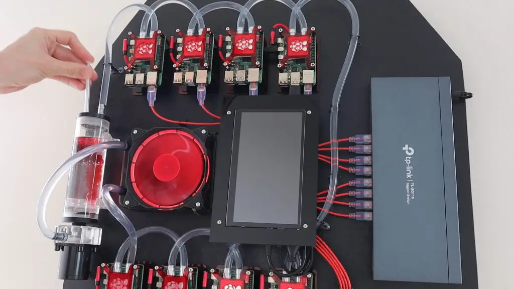
All the cooling water loop needed now was some colour.
Preparing Raspberry Pi OS On The Pis
I prepared a copy of Raspberry Pi OS Lite on 7 microSD cards and a copy of Raspberry Pi OS on the 8th for the master node which has the display attached.

I could then power on the cluster and check that they all boot up. This was done primarily to check that all of the Pis booted up correctly, were able to run on the single power supply and were all recognised and accessible over the network.
I’m not going to get into the software side of the cluster in this post as there are a number of options, depending on what you’d like to do with it and how experienced you are with network computing, but I’ll be covering that in a future post, so make sure that you sign up to my newsletter or subscribe to my Youtube channel to follow my projects.
Running The Completed Water Cooled Raspberry Pi 4 Cluster
With all of the SD cards inserted and the water cooling circuit surviving a 10 minute run with no leaks, I powered up the USB hub to supply power to the Pis.
The system was initially quite noisy as the air bubbles worked their way out of the radiator and cooling water loop, but it eventually settled down. You can hear an audio clip of the cluster running in the video at the beginning of the post.
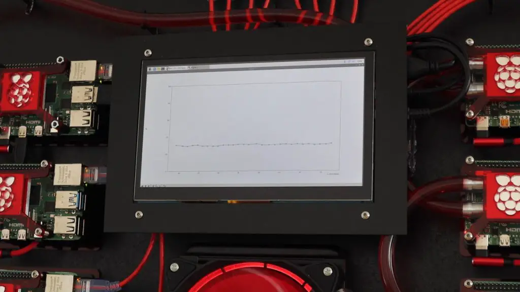
The display is also a nice way to run scripts and visualise information or performance stats for the cluster.
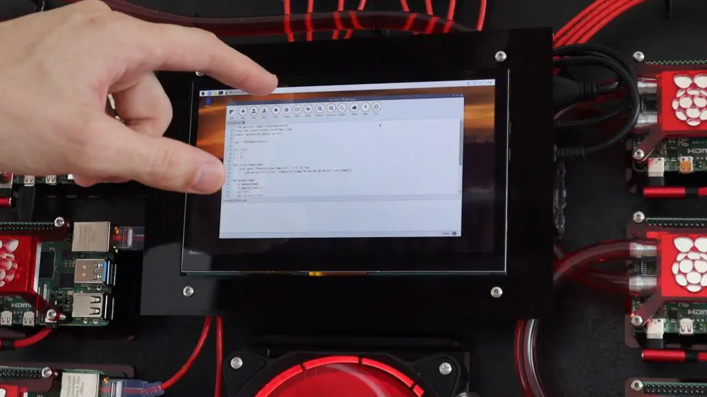
Here I’m just running the script I used previously to display the CPU temperature of the Pi.
Have a look at my follow-up post in which I set up the cluster to find prime numbers and compare its performance to my computers.
I hope you’ve enjoyed following this Raspberry Pi 4 Cluster build with me, please share this post with a friend if you did and leave a comment to let me know what you liked or disliked about the build.
Awesome!!!
Would like to see what you are planning on clustering and it’s performance!
Very clean install and I guess you like red LOL
Thanks Brian! There will definitely be an update soon on how it’s running! I’ll probably do a performance comparison with a PC as well.
Nice work!, what laser cutting machine did you use?
Thanks James. I’ve just got a K40 laser cutter, relatively small and easy to use.
Excellent work! Looks like a fun project. For balancing water flow, consider a “reverse return” arrangement — most commonly used in HVAC systems. Would be interesting to see if there is any performance difference between first and last nodes on the loop w/ and w/o
That’s a great idea, I’ll have a look at testing that out as well. I don’t think there would be any performance difference, as long as the last node is not near the thermal throttling temperature.
Thank you for the amazing article, links, and laser cut design. You’ve inspired me at looking at creating a replica for my little Pi cluster.
If you are interested in running Kubernetes on it for home purposes, check out the rsaspbernetes project if you haven’t already: https://raspbernetes.github.io/docs/installation and the associated https://k8s-at-home.com/ community.
Again, awesome build!
Thank you, I’ll definitely have a look at running Kubernetes on it!
I enjoyed the video, Tried the MPI script on my SLURM cluster and ran it on 4x 7210 Xeon phi nodes (hyperthreding disabled) I got the following results:
100,000 = 2.05s
200,000 = 7.40s
500,000 = 38.52s
1,000,000 = 123.24s
Hi. We’d love to feature this build in a piece I’m writing for HackSpace magazine. Are we ok to use a picture from this post (with full credit of course).
Hi PJ,
Yes sure, that would be great.
Hey, this is probably the coolest pi cluster I have seen. Really GOOD work there. A couple of questions:
Would you have the schematics of the adapter you made to power fan/water pump from the switch?
Did you also power 8 PIs using a 6 port usb hub?
Working on my version of this cluster
Hi Thiago,
Thanks for the great feedback.
I just used a standard 12V 3A power supply (like one for an Arduino) and connected the 12V and GND to the fan, pump and switch individually. There’s nothing really unique to it.
I did initially (using two USB splitters on two ports), this works to just boot them up and idle but if you push the CPUs then they start having supply issues. I landed up adding a second hub so it’s split 4 and 4 now.
Good luck with your build!
OHHHH… one power supply providing power to switch, fan and pump. For some reason I thought you had a switch with PoE and was taking power from the ethernet ports. lol
Yeah it’s just that simple. The Pi’s becoming expensive if you add a PoE hat to each so I choose to not go this route
Hi There, is there anyway to buy the final product?
Hi Assad,
Being a completely custom-built cluster, it would likely be far more expensive to buy than what its perceived value is.
Hi Michael,
I would like to discuss the Details. How much it would be cost? With the delivery costs to Germany?
Well until you tell us something about the software its not a cluster. Its just a bunch of Pis sharing a cooling system and they send their metrics to the “master” so you can monitor and graph them.
Im mainly here for the cluster not the cooling system. 😉
There is a follow-up video and blog post which goes through the setup and running of an example script, this is just the build post.
Great video and instructions Michael. I actually was looking for a price to buy this unit assembled. Are there any for this or your other projects?
For the amount of work that goes into a project like this, selling them would make them unrealistically expensive. I do however sell kits and accessories for some of my other projects – https://www.etsy.com/au/shop/TheDIYLifeCo
Hi Michael,
Just wondering what is running in your cluster today? Have you had a chance to test infoDB? It should be quite useful for all the different projects you run as your central DB for time-based data.
Thanks,
Miguel
not wanting to be negative – to be fair the build does look really good: neat and functional – but the blocks you have used are aluminium whereas the radiator isn’t (will be brass or copper … usually). overtime the aluminium will attack the radiator thru the water via galvanic corrosion – although it shouldn’t be overnight thing! i’m looking into WCing my “array” of PIs, and have been into WCing computers in general in the past (your video was another “inspiration nudger” of many i have watched), so I would advise u look out for (and swap to) copper blocks in future if u intend to keeping the loop running (this is my current “hunt item” for the loop components and organisation I’m going with). also highly recommend some additive if the die doesn’t have any to prevent any growths – and always flush once a year 🙂 that’s my only “complaint”: the rest is really good – looks good, colurs are good and I like the symmetry and the overall layout – nice job.
Thank you for the feedback!
The radiator is aluminium as well, it’s not brass or copper.
Yeah I need to pick up some proper coloured coolant with a anti-microbial and anti-corrosion additives, that’s definitely an issue I’ve noticed on some of my older builds over time.
Have you ever tried to run the High Performance Linpack HPL, I have seen the results for a Turing pi 2 cluster with four nodes of raspberry pi 4Bs and a single raspberry 4B and it would be nice to compare these results with your cluster. I’m thinking about to build a cluster of 24 pi 4Bs for OpenFOAM simulations and maybe the Linpack test on several compute modules like your cluster would be an indicator of performance.
I haven’t tried the Linpack test, I’ll definitely look into it though!