
Made by ElectromakerKits / 3D Printing
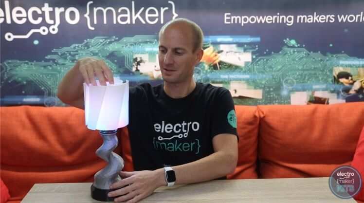
A personalisable, practical and party performing all-in-one mood lamp.
Difficulty: Easy
Platforms: Adafruit, Arduino, noads
Estimated time: 2 hours
License: GNU General Public License, version 3 or later (GPL3+)

|
JST PH 2mm 3-Pin Socket to Color Coded Cable - 200mm | x 1 |
|
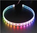
Adafruit NeoPixel LED Strip with 3-pin JST PH 2mm Connector - 60 LED/meter / 0.5 Meter | x 1 |

|
M3 6.0mm Screw Zinc Plated Steel | x 10 |
|
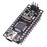
DFRduino Nano | x 1 |
|
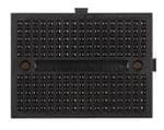
Breadboard Mini Self Adhesive Black | x 1 |
|
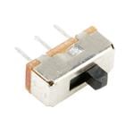
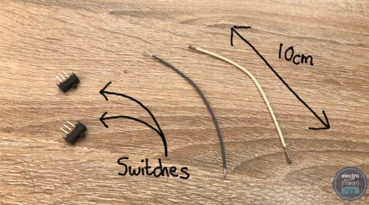
SPDT Slide Switch | x 2 |
|
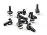
Tactile Switch Buttons 10 pack | x 2 |

|
USB Cable A/MicroB - 3ft | x 1 |
|
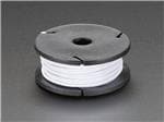
Stranded-Core Wire Spool - 25ft - 22AWG - White | x 1 |

|
Stranded-Core Wire Spool - 25ft - 22AWG - Black | x 1 |
View all
|
|
Arduino IDE |

|
Soldering Iron | x 1 |
|
|
3D Printer | x 1 |
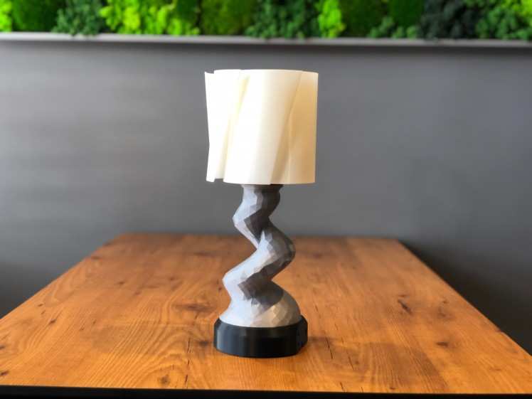
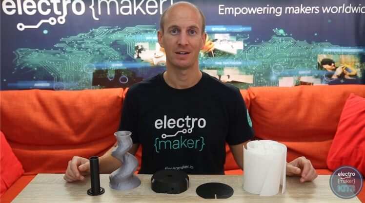
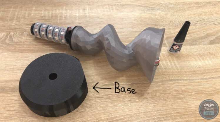
There are five 3D printed components in this project. The Base, Stem, Shade, LED Column, and Cover.
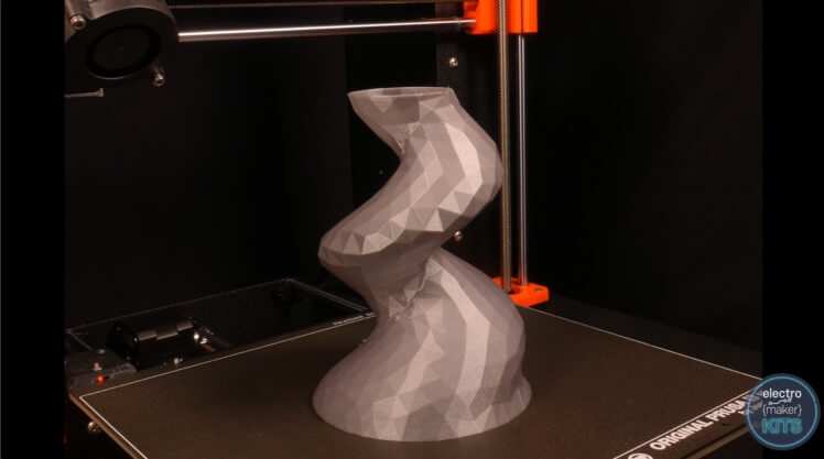
In the downloads section of this project, you will find more than one style of stem or shade to choose from. They are all compatible with each other so the choice is down to your personal taste. You can further personalise your lamp through your choice of filament colour and material.
I'll guide you through assembling one combination of parts to build a Mood Lamp. The instructions are the same if you choose to print a different stem or shade.
Layer height: 0.15mm
Supports: No
Brim: No
Orientation on the print bed: Upside down
Print time: about five hours
Layer height: 0.15mm
Supports: No
Brim: No
Orientation on the print bed: Upright
Print time: about 7 hours
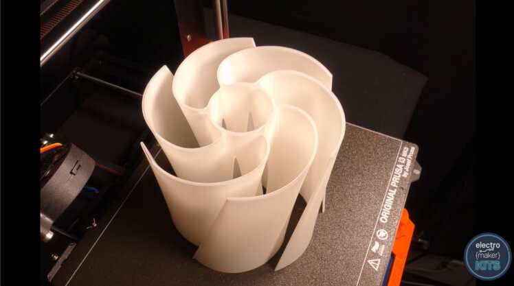
This part was printed with only a single perimeter and no infill in order to allow plenty of light to pass through.
Layer height: 0.15mm
Supports: No
Brim: No
Orientation on the print bed: Upright
Print time: about 10 hours

Layer height: 0.2mm
Supports: No
Brim: No
Orientation on the print bed: Upright
Print time: about 45 minutes
Layer height: 0.20mm
Supports: No
Brim: No
Orientation on the print bed: Upright
Print time: about 1.5 hours

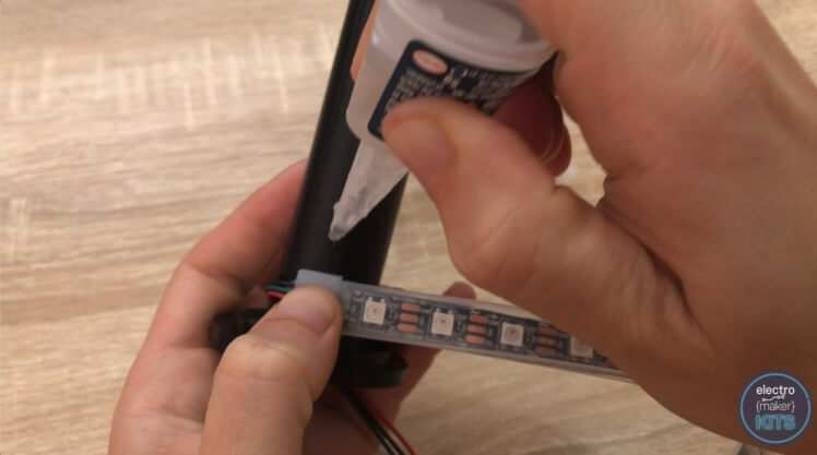
We will start the assembly by attaching the LEDs to the 3D printed 'LED Column'. You could consider using either hot melt glue or super glue. If you choose hot melt glue then you will need to be generous with it. I'm going to use super glue as it has a stronger more permanent hold but will need holding in place whilst it sets.
Unravel the LED strip from the spindle it arrived on and thread the wires through the hole at the base of the LED column.
Before we apply any glue it is a good idea to wrap the LEDs around the column so you get an idea of how far apart they need to be spaced before you start gluing them in place.

Once you know how far you'll space them they can be unravelled and then wrapped around the column again but this time apply glue as you go making sure each bit has cured before moving onto the section.
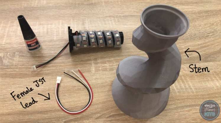
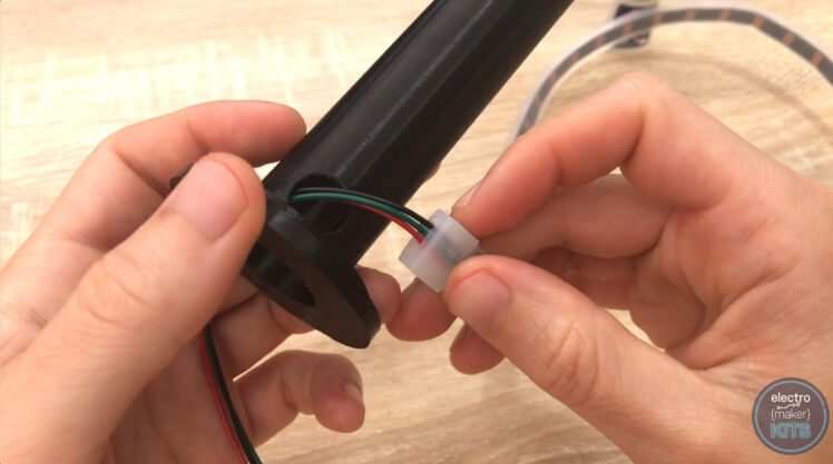
Connect the Female JST connector to the end of the LED wire (they just push together).
Feed the extended wires down though the narrowest end of the stem and pull them out through the wider end.
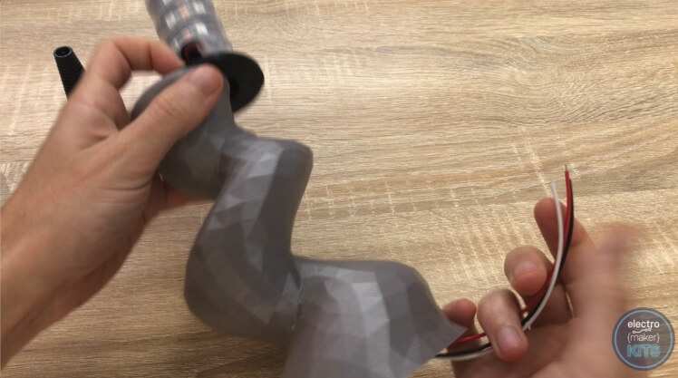
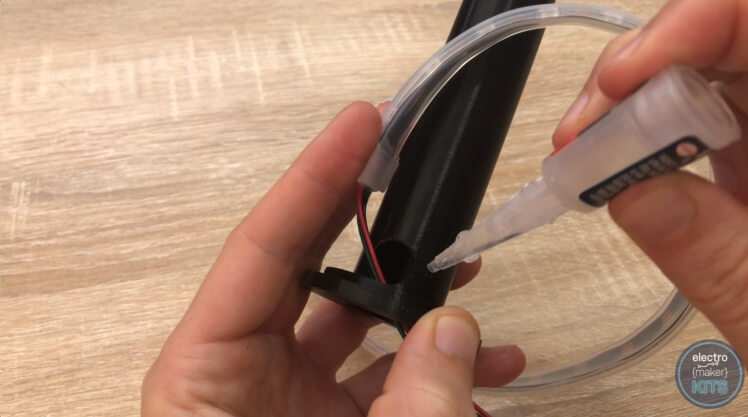
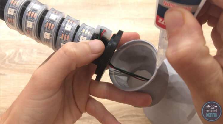
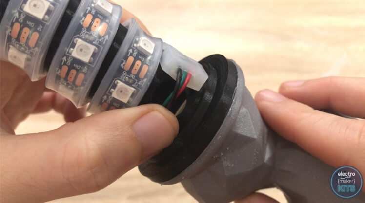
Apply some glue around the rim at the top of the stem and then position the LED holder centrally over the rim and push firmly together whilst the glue sets.
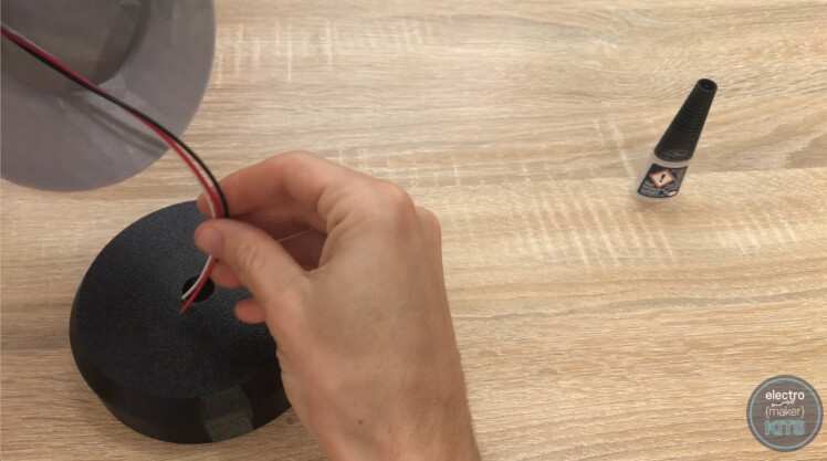
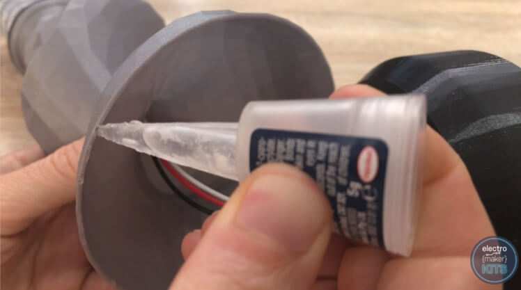
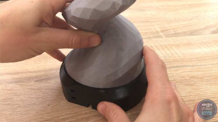
Once set we can take the base of the lamp and thread the wires through the hole on the top. As before, apply some glue to the rim at the other end of the stem and carefully position it onto the base. Before the glue begins to set turn it around and make sure your happy with its positioning as seen from all angles.
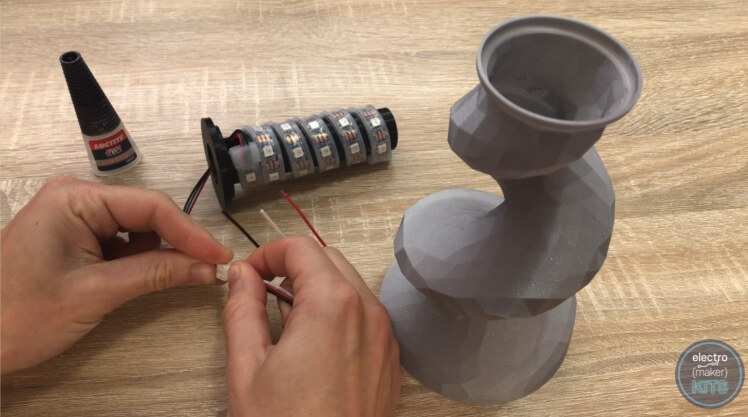
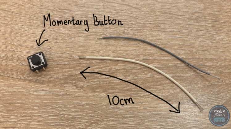
Cut and strip two 10cm lengths of wire.
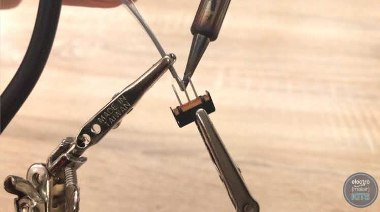
Solder one of these to the centre leg of one switch and then repeat with the other pair.
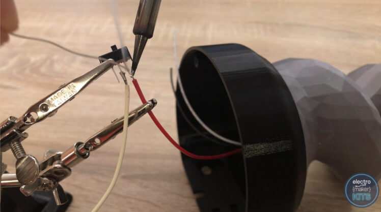
Take the red wire coming from our LEDs (this is the 5v power connection) and solder this to one of the unused legs on one of the switches.
Repeat this again for the white wire coming from the LEDs with the other switch. The white wire is the digital input for the LEDs.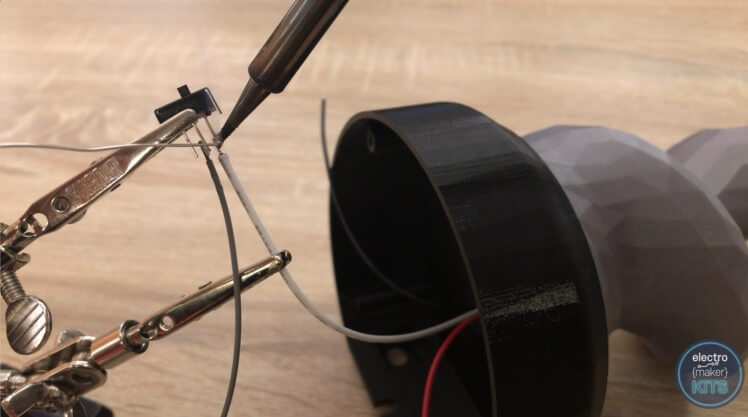
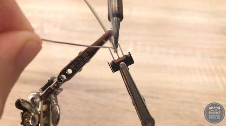
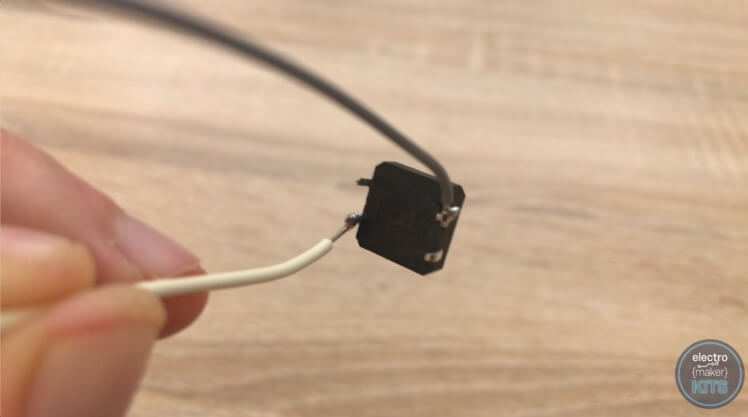
Prepare another two 10cm lengths of wire ready to solder to the momentary push button.
Solder each wire to two diagonally opposite legs on the back of the push button.

Use some glue to fix the two sliding switches into their hole from inside the base of the lamp. Be careful to not let the glue get in the sliding mechanism or it may prevent it from working properly.
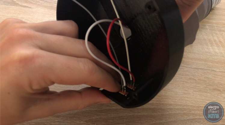
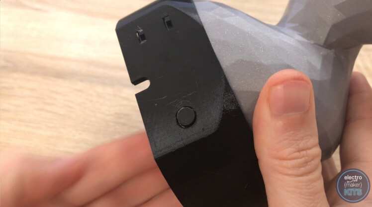
Now fix the button into its place, again, be careful to only get glue on the outside of the button housing and not onto the button itself.
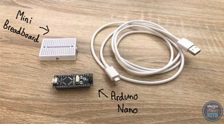
Add the Arduino Nano onto the top of the breadboard and connect the USB cable to it and the other end into your PC. Open the Arduino IDE on your PC. If you have not yet installed this, you can find the free download and instruction here: https://www.arduino.cc/en/main/software 
We need to install a couple of libraries. The first one is Adafruit's Neopixel library.
To do this, in the Arduino IDE go to:
Sketch >> Include library >> Manage Libraries
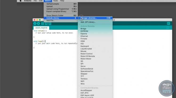
From here search for 'Neopixel'. Look for Adafruit Neopixel by Adafruit and install the latest version.
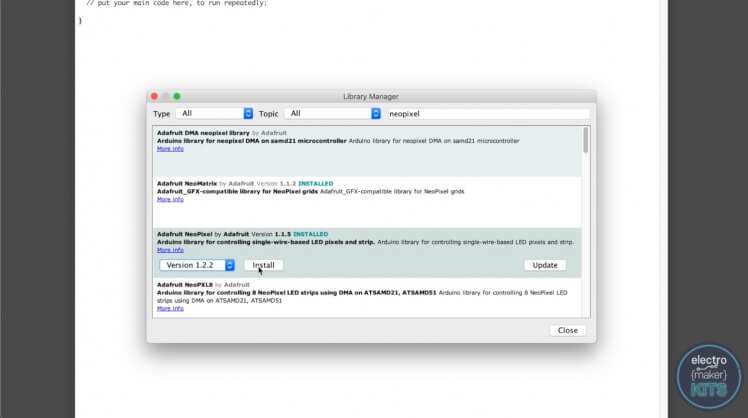
You then close the windows after the install is complete.
The second library you need it the WS2812FX library. This can be downloaded from https://github.com/kitesurfer1404/WS2812FX

You can download a zip of the repository by clicking 'Clone or Download' and then 'Download ZIP'
Extract the downloaded file into your Arduino IDEs Library folder.
The last bit of code you need is the one we will upload to our Arduino Nano for this project. You will find the file available to download at the bottom of this page in the downloads section.
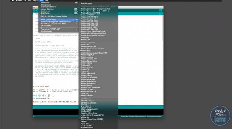
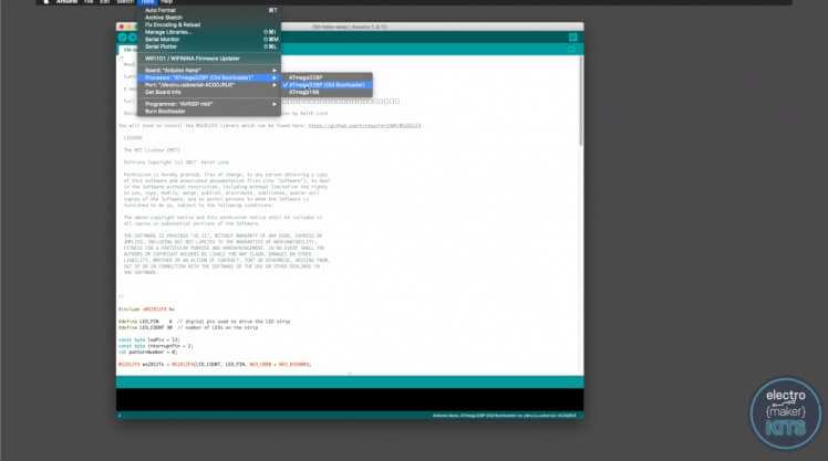
Before you can upload the code you need to ensure you have a correct board type and processor selected int the Arduino IDE. To do this, head to 'Tools' in the menu and ensure you have the Board Type of 'Arduino Nano' selected and the Processor set as 'ATmega328P (Old bootloader)'.
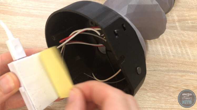
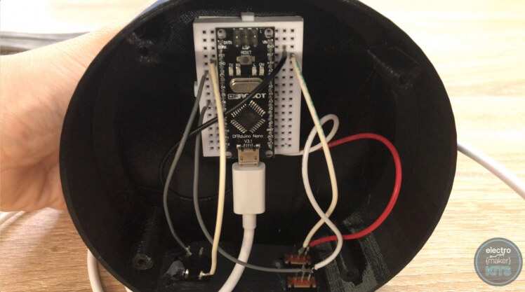
After the upload has completed you can disconnect the USB cable from the PC. Leave the other end attached to the Arduino to help us position the Arduino and Breadboard inside the base of the lamp. To do this, peel of the protective sheet on the self-adhesive side of the breadboard and push it firmly into place on the underside of the lamp base.
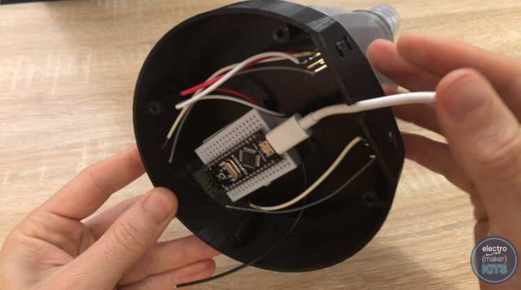
At this stage, you can choose between either inserting the wires into the breadboard points to connect them to the Arduino (which would make it easy to repurpose your Arduino in the future) or soldering the wires to the top side of the Arduino - a more permanent solution.
If you choose to utilise the breadboard as I'm going to do then you will likely find the wires easier to insert if you 'tin' them first. This involves applying some solder to the strands of wire so that they come together as one more rigid wire which is easier to insert into the breadboard.
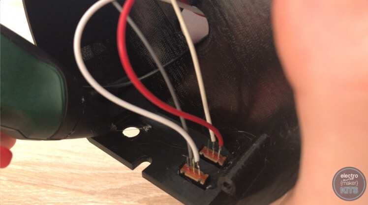
The switch which is connected to the Red 5V lead coming from the LEDs should have its unconnected wire connected to the 5V on the Arduino.
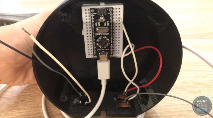
The other switch, which is connected to the LEDs white digital in lead, should have its free wire connected to D6 on the Arduino.
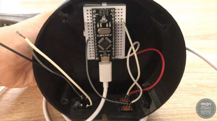
The remaining black ground lead coming from the LEDs is connected to a ground connection on the Arduino.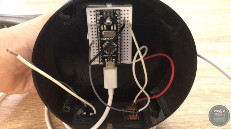
One wire coming from the momentary button is also connected to a ground point on the Arduino.
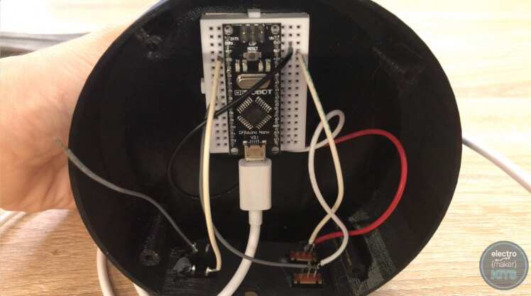
The remaining wire coming from the momentary button is connected to D2.
If you now connect the USB cable coming from the Arduino to a power supply such as a computer, battery pack or wall socket you will be able to check that all your switches and buttons work as intended. One of the switches will turn the LEDs on and off, the other will pause the sequence. The button will change the pattern.
If everything works we can proceed with adding the cover. If you encounter something that is not behaving as expected carefully check back through your work so far.
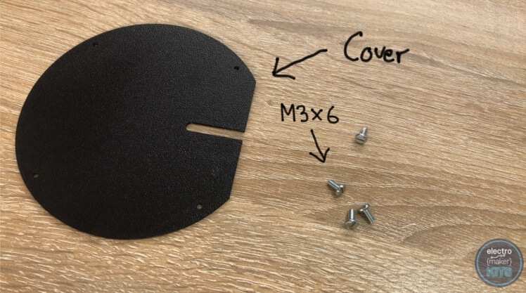
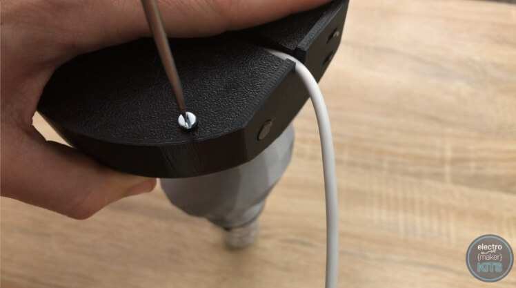
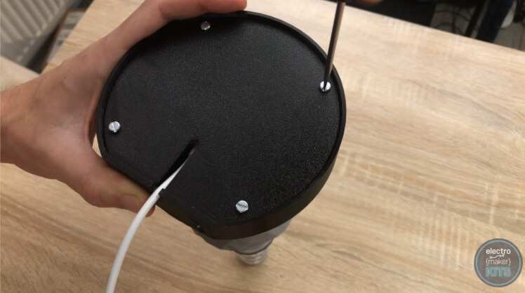
The cover is secured in place with three of the M3 x 6 bolts. It's a simple case of inverting the lamp and securing it onto the underside of the base. Take care not to trap the USB wire by feeding it through the provided slot.
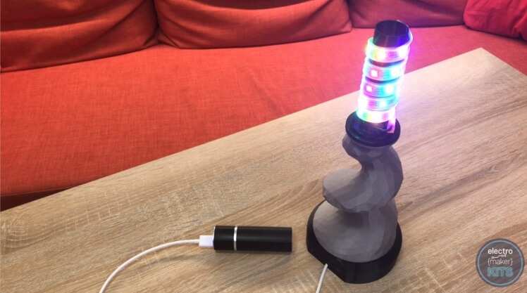
The last task is adding the shade, and this is also the easiest one. After you have 3D printed your shade it is just lowered down over the LED column and rests on the top of the stem.
Don't forget you can print other shade designs in alternative colours whenever you fancy a different style.

We've preprogrammed some useful light sequences; a solid bright white to use as a practical lamp, a slowly changing atmospheric pattern for relaxation, a lively party program for when you're hosting your mates and a few more for you to try out for yourself.
The MyMiniFactory community has produced many different designs for you to download and print! More info here.


Leave your feedback...